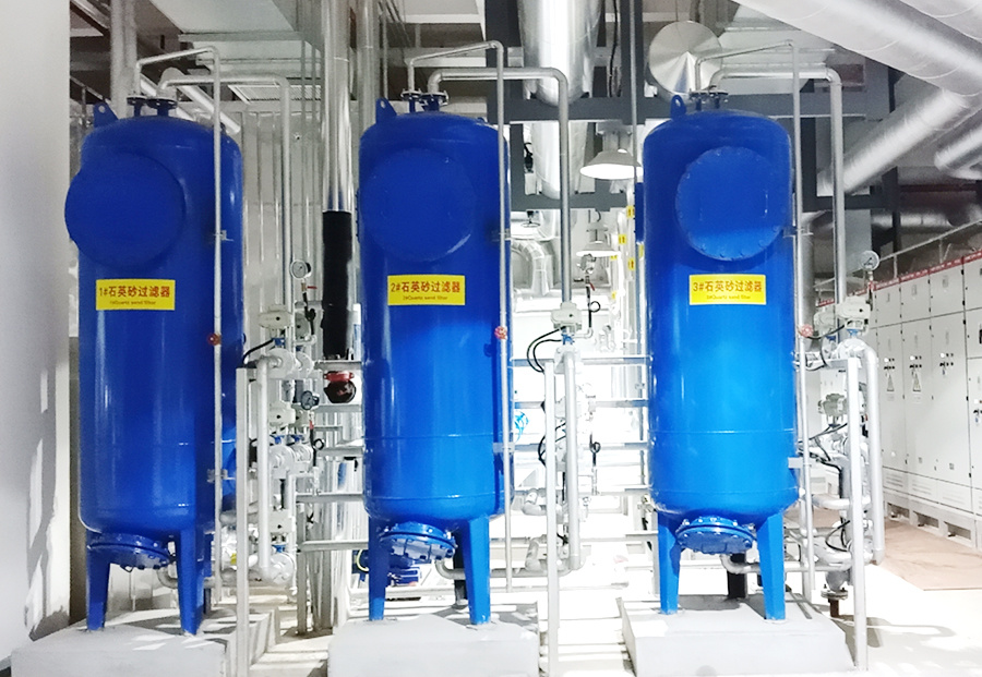
Multimedia filter
Tags:
Belongs to Category:
Multimedia filter
Product Description
► Operating Principle
A mixed bed refers to a system where water sequentially passes through a cation bed containing hydrogen-type cation exchange resin and an anion bed containing hydroxide-type anion exchange resin. The hydrogen-type cation exchange bed is used to remove cations from the water; the hydroxide-type anion exchange bed is used to remove anions from the water. Various mineral salts in the water can be essentially removed through the mixed bed. To achieve better desalination, the cation bed is loaded with strong acid cation exchange resin, and the anion bed is generally loaded with strong base anion exchange resin.
► Application Range
Mixed beds are generally placed after electrodialysis or reverse osmosis devices (or directly applied to water with lower salt content) for further desalination of water to produce high-purity water. They are widely used in electronics, chemical, pharmaceutical, nuclear energy, and power industries.
► Equipment Composition and Performance
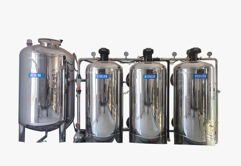
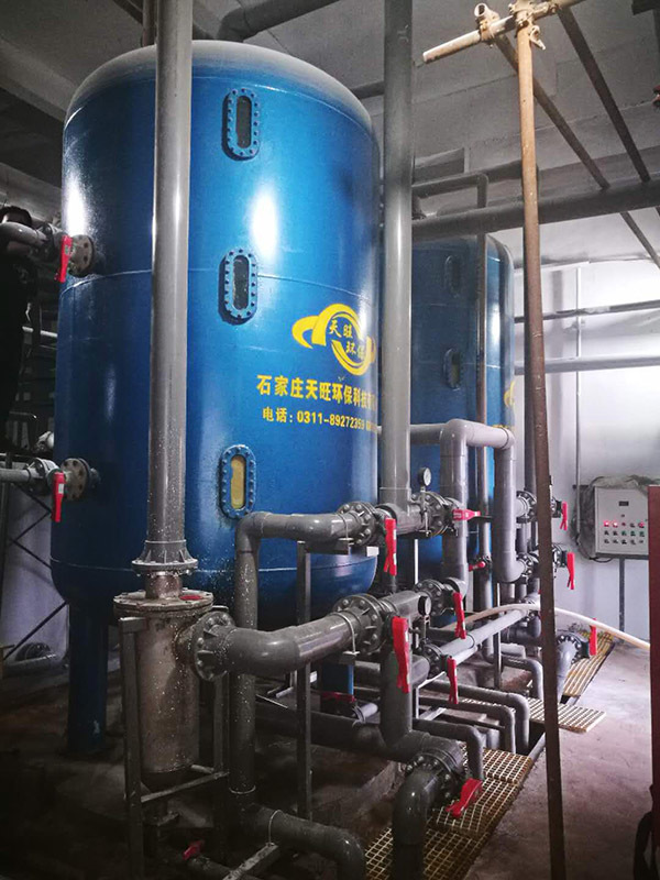
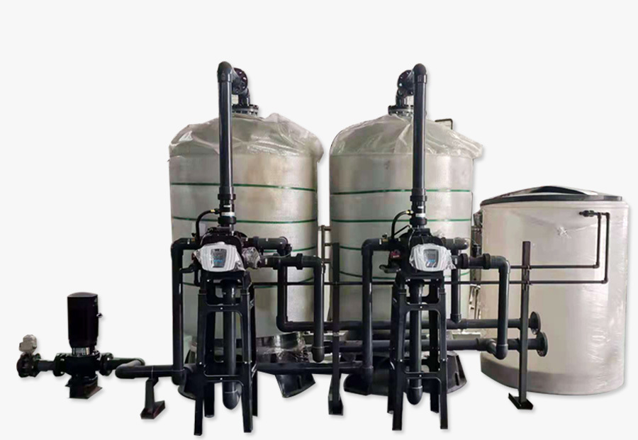
Mixed bed shells are made of materials such as fiberglass reinforced plastic, acrylic, stainless steel, carbon steel, and corrosion-resistant materials. The outer shape is cylindrical, with a diameter of Ø200-2500mm, and a water production capacity ranging from 0.5t/h to 98t/h. The cation bed is loaded with strong acid cation exchange resin, and the anion bed is loaded with strong base anion exchange resin. The loading height is generally 1000-2400mm. Small filter cap-type equipment does not have a support layer at the bottom, while medium and large-sized equipment has a multi-level quartz sand support layer with different particle sizes. The top layer of the resin in the counter-current regeneration fixed bed has a 200mm thick quartz sand pressure layer. The operating pressure of acrylic columns is ≤0.15MPa, and the operating pressure of equipment made of other materials is ≤0.6MPa. The cation bed is equipped with an acid tank and an acid pump regeneration system, while the anion bed is equipped with an alkali tank and an alkali pump regeneration system.
► Preparation Work Before New Equipment Operation
1. Grading of the support layer for medium and large-sized equipment (except for small acrylic equipment)
Thickness and grading of the quartz sand support layer
|
Layers (from top to bottom) |
Particle size (mm) |
Ø<1600 layer thickness mm |
Ø1600-Ø2500 layer thickness mm |
|
1 |
1-2 |
200 |
200 |
|
2 |
2-4 |
100 |
150 |
|
3 |
4-8 |
100 |
100 |
|
4 |
8-16 |
100 |
150 |
|
5 |
16-25 |
250 |
250 |
Note: Ø1600, Ø2500 refer to the equipment diameter.
2. Resin filling:
(1) Thoroughly clean and wash all parts of the ion exchanger.
(2) For small exchangers without a support layer, add a certain height of water before filling the resin to prevent the resin from impacting the bottom of the exchanger.
(3) Thoroughly rinse the quartz sand support layer.
(4) The resin filling height for small and medium-sized exchangers is 2/3 of the effective height of the column. For large exchangers, the filling height is determined based on the actual water quality and water volume.
After meeting the requirements, seal the exchanger. Backwash and settle the resin, drain the water, then open the exchanger, remove the fine particles or soft balls of resin that float to the top of the resin layer. If the resin layer height does not meet the requirements, add more resin.
► Resin Regeneration
(1) Regeneration of strong acid cation exchange resin in the cation bed:
1. Backwashing of the cation bed:
Open the main water inlet valve (7), regulating valve (11), and backwash valve (12). Water enters from the bottom of the equipment, and the top outlet valve (14) discharges. The resin is evenly loosened and expanded. Then, the water flow rate can be increased, but it should not exceed the resin. Wash until the effluent is clear. Finally, drain from the bottom outlet valve (13).
2. Preparation of regenerant:
The regenerant is prepared by mixing chemically pure hydrochloric acid with high-purity water to form a 5% concentration regenerant solution. The amount used is about twice the volume of the resin.
3. Co-current regeneration: The prepared regenerant is pumped into the column through the acid inlet valve (9) and water inlet valve (10) using an acid pump. The flow rate is generally controlled at 4-8m/h, and the pressure should not be too high. The liquid level should be maintained 100mm above the resin layer. Soak for 1.5-2 hours, then open the bottom outlet valve (13) to drain the acid solution from the column.
4. Counter-current regeneration: Open the top outlet valve (14). The regenerant is pumped into the column by the acid pump through the acid inlet valve (9), regulating valve (5), and backwash valve (12). The regenerant flow rate is 1.6-2m/h, and the time is 40-60 minutes. Soak for 1.5-2 hours, then drain the acid solution from the column through the bottom outlet valve (13).
5. Dynamic regeneration: Follow the co-current regeneration procedure. The flow rate must be slow. Rinse the resin for 15-30 minutes until the regenerant is used up.
6. Forward washing: Use the effluent from the previous stage (electrodialysis produced fresh water, reverse osmosis produced fresh water) to rinse the resin through the main water inlet valve (7) and water inlet valve (10) from the top of the equipment. The flow rate must be uniform. When the pH value of the effluent from the bottom outlet valve (13) reaches 5-6, stop rinsing.
7. Operation: Open the main water inlet valve (7), water inlet valve (10), and water outlet valve (12) to supply water to the anion bed.
(2) Regeneration of strong base anion exchange resin in the anion bed
1. Backwashing of the anion bed:
Open the main water inlet valve (7), regulating valves (11, 16), and anion bed backwash valve (17). Water enters from the bottom of the equipment, and the top outlet valve (19) discharges. The resin is evenly loosened and expanded. Then, the water flow rate can be increased, but it should not exceed the resin. Wash until the effluent is clear.
2. Preparation of regenerant:
The regenerant is prepared by mixing chemically pure sodium hydroxide with high-purity water to form a 5% concentration regenerant solution. The amount used is about twice the volume of the resin.
3. Co-current regeneration: Introduce the prepared regenerant into the column using an alkali pump via the alkali inlet valve (8), regulating valve (11), and anion bed inlet valve (15). The flow rate is generally controlled at 4-8 m/h. Avoid excessive pressure, maintaining the liquid level 10 cm above the resin surface. Soak for 1.5-2 hours, then open the bottom drain valve (18) to drain the alkali solution from the column.
4. Counter-current regeneration: Open the top drain valve (19). Introduce the regenerant using an alkali pump via the alkali inlet valve (8), regulating valve (11, 16), and anion bed backwash valve (17). The regenerant flow rate is 1.6-2 m/h for 40-60 minutes. Soak for 1.5-2 hours, then drain the acid solution from the column via the bottom drain valve (18).
5. Dynamic regeneration: Operate the valves according to the co-current regeneration procedure. Maintain a slow flow rate. Rinse the resin for 15-30 minutes until the regenerant is completely used.
6. Forward washing: Use the upstream product water (electrodialysis produced freshwater, reverse osmosis produced freshwater) to rinse the resin from the top of the equipment via the total inlet valve (7), regulating valve (11), and anion bed inlet valve (15). Maintain a uniform flow rate. Stop rinsing when the effluent pH value at the bottom drain valve (18) reaches 8-9.
7. Operation: The product water from the cation bed enters the anion bed via the anion bed inlet valve (15) and is supplied to the downstream equipment via the anion bed outlet valve (17).
► Notes
① Newly regenerated ion exchange columns require rinsing for ten to twenty minutes. The water quality is initially poor; normal operation should only commence after the water quality becomes acceptable.
② When supplying water to the ion exchange column, always open the air vent valve first. Close it only after the column is completely filled with water.
③ If the effluent from a new column is substandard, immediately stop the effluent and pause for several hours before resuming operation. The effluent water quality will significantly improve.
④ When the inlet water temperature is low in winter during anion exchange resin regeneration, the alkali solution should be heated to above 20℃.
⑤ Avoid high-speed, high-flow backwashing before each regeneration. After 10-20 regeneration cycles of the cation bed, a high-speed, high-flow backwash can be performed.
⑥ During backwashing, observe whether the resin rises slowly. If the resin clumps and rises without dispersing, immediately close the inlet valve and open the drain valve. Resume backwashing after the resin has loosened. After backwashing, do not empty the water from the column; generally maintain a 20cm water cushion above the resin surface. Otherwise, a large number of bubbles will be generated when the regenerant flows in, affecting the regeneration effect.
Diagram of Cation and Anion Bed Pipes and Valves
Valve Summary Table
|
Serial Number |
Valve Name |
10 |
Cation Bed Inlet |
|
1 |
Acid Tank Pressure Reducing Valve |
11 |
Regulating Valve |
|
2 |
Acid Solution Inlet Pump |
12 |
Cation Bed Outlet |
|
3 |
Acid Solution Discharge |
13 |
Cation Bed Discharge |
|
4 |
Alkali Tank Pressure Reducing Valve |
14 |
Cation Bed Air Vent |
|
5 |
Alkali Solution Inlet Pump |
15 |
Anion Bed Inlet |
|
6 |
Alkali Solution Discharge |
16 |
Regulating Valve |
|
7 |
Total Inlet Valve |
17 |
Anion Bed Outlet |
|
8 |
Alkali Inlet Valve |
18 |
Anion Bed Discharge |
|
9 |
Acid Inlet Valve |
19 |
Anion Bed Air Vent |
► Mixed Bed Operating Principle
A mixed bed ion exchanger contains a certain proportion of strong acid cation exchange resin and strong base anion exchange resin in a single exchanger. When the primary demineralized water (electrodialysis, reverse osmosis, or mixed bed effluent) flows through the uniformly mixed resin, high-purity water is obtained. This method is more advanced, equivalent to tens of thousands of mixed beds operating simultaneously, resulting in high-quality purified water. It is the optimal method for preparing pure water and ultrapure water.
► Resin Filling Status
The volume ratio of anion and cation exchange resins in the mixed bed is 2:1. There is an acid drain pipe at the bottom of the ion exchanger, used to control the acid interface during cation resin regeneration so that it does not exceed the cation resin interface.
Total resin height in the mixed bed exchanger: Approximately 2/3 of the effective height of the exchanger for small and medium-sized units; for large units, it depends on the actual water quality and quantity.
► Mixed Bed Operation
Generally, it involves eight steps: backwashing, stratification, anion resin regeneration, forward washing, cation resin regeneration, rinsing, mixing, and forward washing.
1. Backwashing:
Water enters from the bottom and exits from the top air vent. The resin expands and loosens evenly. The water flow rate can be increased, but it should not wash out the resin. Continue until the effluent is clear.
Valve operation: Open the inlet valve, regulating valve, backwash valve, outlet valve, and air vent valve.
2. Stratification:
Utilize the difference in specific gravity between anion and cation resins (cation resin specific gravity is 1.23-1.28, anion resin specific gravity is 1.06-1.11) to achieve stratification through backwashing; the backwashing stratification flow rate is approximately 10 m/h (backwashing can also remove some impurities and foreign objects, ensuring normal operation in the next cycle). After backwashing loosens the resin in the column, close the water source and allow the resin in the column to settle slowly. The heavier cation resin will settle at the bottom of the column, while the anion resin will settle at the top of the column (observe the stratification from the outside: the anion resin at the top is light in color, and the cation resin at the bottom is dark in color). If the stratification is not ideal, repeat the above steps until the anion and cation resins are completely separated.
Precautions
① Backwashing must be thorough, ensuring that the resin in the mixed bed is completely loosened (the resin must have sufficient expansion height during operation).
② The resin must settle slowly in the column.
③ The stratification result must be completely sufficient (avoid dead corners near the lower water distribution).
3. Anion exchange resin regeneration:
(1) Preparation of regenerant: The regenerant is a 5% NaOH solution, with a dosage of 2-3 times the volume of the anion resin.
(2) Use of regenerant: Pump the prepared regenerant into the column (note that the pressure should not be too high), keeping the liquid level about 10 cm above the resin level, soak for 1.5-2 hours, and drain the waste alkali solution from the column.
Valve operation: Open the alkali solution inlet pump valve, alkali pump pressure reducing valve, alkali inlet valve, mixed bed water inlet valve, and vent valve (the alkali pump pressure reducing valve is used to adjust the alkali inlet pressure; when discharging, open the lower discharge valve).
(3) Dynamic regeneration: Pump the remaining regenerant into the column, the flow rate (3-5 m/h) must be slow, rinse the resin for 15-30 minutes until the regenerant is used up.
Valve operation: Open the alkali solution inlet pump valve, alkali pump pressure reducing valve, mixed bed alkali inlet valve, mixed bed water inlet valve, vent valve, and discharge valve (the alkali pump pressure reducing valve is used to adjust the alkali inlet pressure).
4. Forward washing: Rinse the resin from the top with primary deionized water, the flow rate (10-15 m/h) must be uniform, test the effluent from the bottom of the ion exchange column with pH paper, and stop rinsing when the pH value reaches 8-9.
Valve operation: Open the water inlet valve, mixed bed water inlet valve, vent valve, and discharge valve.
5. Cation exchange resin regeneration:
(1) Preparation of regenerant: The regenerant is a 5% HCL solution, with a dosage of 2-3 times the volume of the cation resin.
(2) Use of regenerant: Pump the prepared regenerant into the column (note that the pressure should not be too high), keep the liquid level near the cation resin surface in the middle drain pipe, soak for 1.5-2 hours, and drain the waste acid solution from the column.
Valve operation: Open the acid solution inlet pump valve, acid pump pressure reducing valve, acid inlet valve, regulating valve, and middle drain outlet valve (the acid pump pressure reducing valve is used to adjust the acid inlet pressure; open the discharge valve when discharging).
(3) Dynamic regeneration: Pump the remaining regenerant into the column, the flow rate must be slow, rinse the resin for 15-30 minutes until the regenerant is used up.
Valve operation: Open the acid solution inlet pump valve, acid pump pressure reducing valve, acid inlet valve, regulating valve, outlet valve, and middle drain valve (the acid pump pressure reducing valve is used to adjust the acid inlet pressure; open the discharge valve when discharging).
6. Rinsing: Rinse the resin from the bottom with primary deionized water, discharge from the middle drain pipe, the flow rate (approximately 15 m/h) must be uniform, test the effluent from the middle drain pipe of the ion exchange column with pH paper, and stop rinsing when the pH value reaches 5-6.
Valve operation: Open the water inlet valve, backwash valve, and middle drain valve; when stopping rinsing, open the discharge valve for about 1-2 minutes.
Precautions:
When introducing the regenerant, be sure not to allow the acid to exceed the cation resin liquid level, otherwise the anion resin will be affected by the acid and become ineffective.
Key points: During the regeneration of anion and cation resins, the soaking must be sufficient, the regenerant must be prepared uniformly, and the regeneration materials must be clean and uncontaminated. After rinsing, the concentration of acid and alkali must reach a level where they can be neutralized to neutral after mixing.
7. Methods for mixing the mixed bed:
(1) Mixing steps using compressed air (or nitrogen, etc.):
① Add primary deionized water to the column, keeping the liquid level 15-20 cm above the resin level.
Valve operation: Open the water inlet valve and vent valve.
② Connect clean, dry, oil-free compressed air, introduce air from the bottom, and discharge from the top valve, controlling the air pressure at 0.1-1.5 MPa, allowing the resin in the column to loosen into a boiling state.
Valve operation: Open the lower air inlet valve or discharge valve (connect compressed air) and vent valve.
③ Close the compressed air and quickly drain from the bottom until the water is completely drained.
④ Repeat the above operation 4-6 times until the mixture is completely uniform before starting to use.
(2) Mixing steps using a vacuum pump:
① Add primary deionized water to the column, keeping the liquid level 15-20 cm above the resin level.
Valve operation: Open the water inlet valve and vent valve.
② Connect the top vent valve to the vacuum pump, draw a vacuum from the top, and introduce air from the bottom discharge valve, controlling the vacuum pressure at 0.15-0.2 MPa, allowing the resin in the column to loosen into a boiling state. Observe from the outside until the anion and cation resins in the column are mixed uniformly.
Valve operation: Open the top vent valve (connected to the vacuum pump) and the bottom drain valve.
③ Close the vacuum pump and quickly drain the water from the bottom until all the water is drained.
④ Repeat the above operation 4-6 times until completely mixed evenly, then you can start to reuse.
Precautions:
① Drainage must be timely to prevent stratification during resin settling.
② Thorough and even mixing is necessary to ensure regeneration quality and effluent water quality.
③ Carefully check to prevent compressed air from bringing in oil stains to avoid resin contamination.
8. Positive washing: After mixing the anion and cation resins, inject the primary demineralized water from the top through the inlet valve and drain it from the bottom valve; rinse the resin with a flow rate of 10-15 m/h until the effluent meets the standard.
9. Normal operation:
(1) Inject primary demineralized water into the exchange column, open the vent valve, close the vent valve after filling with water, open the outlet valve, and measure the effluent water quality of the ion exchange column at the outlet valve. Generally, after running for 15-25 minutes, the effluent can reach normal, and after the effluent meets the standard, it can be operated (at a speed of 20-40 m/h).
Valve operation: Open the inlet valve, outlet valve, and vent valve. Close the vent valve after filling with water. Precautions:
① Newly regenerated ion exchange columns require rinsing for ten to twenty minutes. The water quality is initially poor; normal operation should only commence after the water quality becomes acceptable.
② For the ion exchange column, the vent valve must be opened first, and then closed after the column is completely filled with water.
③ If the effluent from the new column does not meet the standard, stop the effluent immediately, stop for several hours, and then run again. The effluent water quality will be greatly improved.
Valve Summary Table
|
Serial Number |
Valve Name |
9 |
Acid Inlet Valve |
|
1 |
Acid pump pressure reducing valve |
10 |
Mixed bed inlet |
|
2 |
Acid Solution Inlet Pump |
11 |
Regulating Valve |
|
3 |
Acid Solution Discharge |
12 |
Mixed bed outlet |
|
4 |
Alkali pump pressure reducing valve |
13 |
Inlet valve |
|
5 |
Alkali Solution Inlet Pump |
14 |
Mixed bed drain valve |
|
6 |
Alkali Solution Discharge |
15 |
Mixed bed middle drain |
|
7 |
Inlet valve |
16 |
Vent valve |
|
8 |
Alkali Inlet Valve |
|
|
Leave a Message
Fill in your phone number and E-mail information, and we will contact you within one working day to solve your problems as soon as possible.
-- Recommended --
Shijiazhuang Tianwang Environmental Protection Technology Co., Ltd.
Shijiazhuang Tianwang Environmental Protection Technology Co., Ltd. is a high-tech enterprise specializing in the research and development, manufacturing and sales of water treatment equipment.
Contact Information
Production address: No. 9, Fengchan Road, Economic and Technological Development Zone, Shijiazhuang City
Office Address: 25th Floor, Block C, No. 310 Changjiang Avenue, Shijiazhuang High-tech Development Zone
Contact Number:
0311-89272359 0311-68039237
Enterprise Email:
twhbkj@163.com
Website: en.sjztwhb.com


